The Arduino Water Sprinkler Controller is a centralized controller for a three 9v water sprinklers (electrovalves). The electric scheme is specific for the type of electrovalves I own (Gardena 1251-U Valvola Cordless 9V) but could easily modified to drive other type of electrovalves, provided that are bistable.
Table of contents
- Bistable electrovalves
- Gardena 1251-U electrovalve
- Arduino controller
- Activating electrovalves
- Wiring everything
- The code
- Final touches
Bistable electrovalves
A bistable electrovalve is a valve which preserves its state once it is activated. Generally it needs a positive impulse for a short time period (in the order of ms). Once it is opened, it stays opened even when the impulse ends. Then a negative impulse (perhaps of a different voltage and a different amount of current) closes it. It is less power consumptive w.r.t. monostable valves, since it requires voltage only for very short amount of time when state change are require. From the other way, monostable valves, require to receive power as long as it is required to stay opened.
Gardena 1251-U electrovalve
The Gardena 1251-U electrovalve is a bistable electrovalve which can be controlled manually or through a standard RCA interface. The electrical specifications provided by the productor are the following:
| State Voltage Current | Duration | Submitted |
|---|---|---|
| ON | 7-9V | 207-210mA |
| OFF | -1.6V | 50mA |
Given these requirements an Arduino could be used to drive as many electrovalves as allowed by the output ports of the used platform.
The 1251-U electrovalves are generally coupled to a battery powered controller which is installed on top of the electrovalves and is programmed using a programmer which once programs the controller, could be removed. The solution is shown in the following circuit:
Arduino controller
When I bought my house, I found a water sprinkler installation using these electrovalves. However, the former owner did not provide me with the programmer, so I had to activate the valves manually. This is not convenient when I am not at home. Moreover, the levers for manual activation are very consumed and are nearly broken. For this reasons, instead of buying it for about €70 (around $85) or risk to broke my valves, I decided to build my own controller, which could be programmer with a timer and/or manually, using buttons instead of levers.
Since electrovalves are similar to DC motor from an electric point of view, I decided to use a motor shield attached to the arduino. It can be used to control up to 4 electrovalves. The bill of materials for controlling three electrovalves follows:
- 1x Arduino UNO or similar (Uno-like form factor is preferred to attach the shield)
- 1x Arduino motor shield (v1 or v2 does not matter)
- 1x ds3231 i2c clock breakout board
- 3x Diodes
- 3x 150 Ohm resistors
- 3x Momentary (normally closed push buttons), better if water proof.
- 1x ON-OFF switch, better if water proof
- 3x RCA connectors
- 3x RCA male-male cables
- 1x 9v power source (batteries could be used but I suggest to use a power adapter)
- Some jumper wires
Activating the electrovalves
Since the activation and deactivation of the electrovalve requires opposite voltage, the drivers in the motor shield helps to provide positive and negative voltage. However, since the rates and currents are different, simply attach the ouput of the DC motors of the motor shield is not sufficient. A strategy to vary the voltage and current of the output (9v 210ma for opening, -1.6v 50mA for closing) is required.
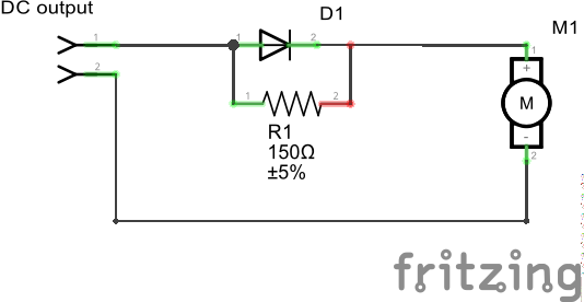
Using this circuit, assuming the + terminal is at top, when a positive 9v voltage is applied, the top branch acts as a short circuit and the current flows freely through the diode and activates the valves, while when a negative 9v voltage is applied, the top branch acts as an open circuit and the current must pass through R1, the voltage drops to -1.6v and the current is limited according to the specification. Actually another resistor should be applied in series with the diode, but since the valve opens even without using it, I decided not to include it.
This is the main brick of the system.
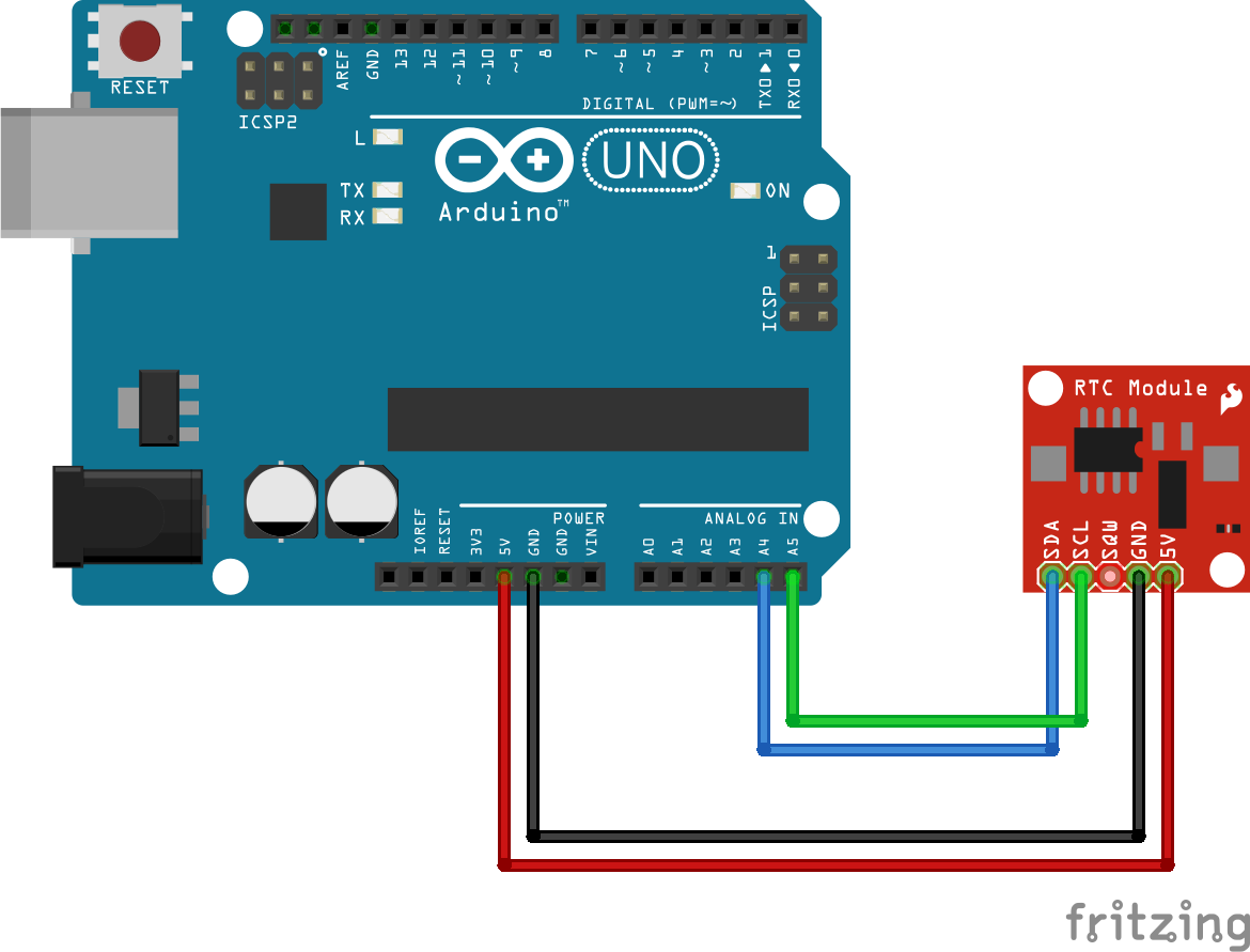
The second part of the circuit is the wiring of the ds3231 breakout board, which is done using the standard i2c arduino bus wiring, using 4 wires, Vcc to arduino 5v, GND to GND, SDA to A4, SCL to A5, as shown in figure:
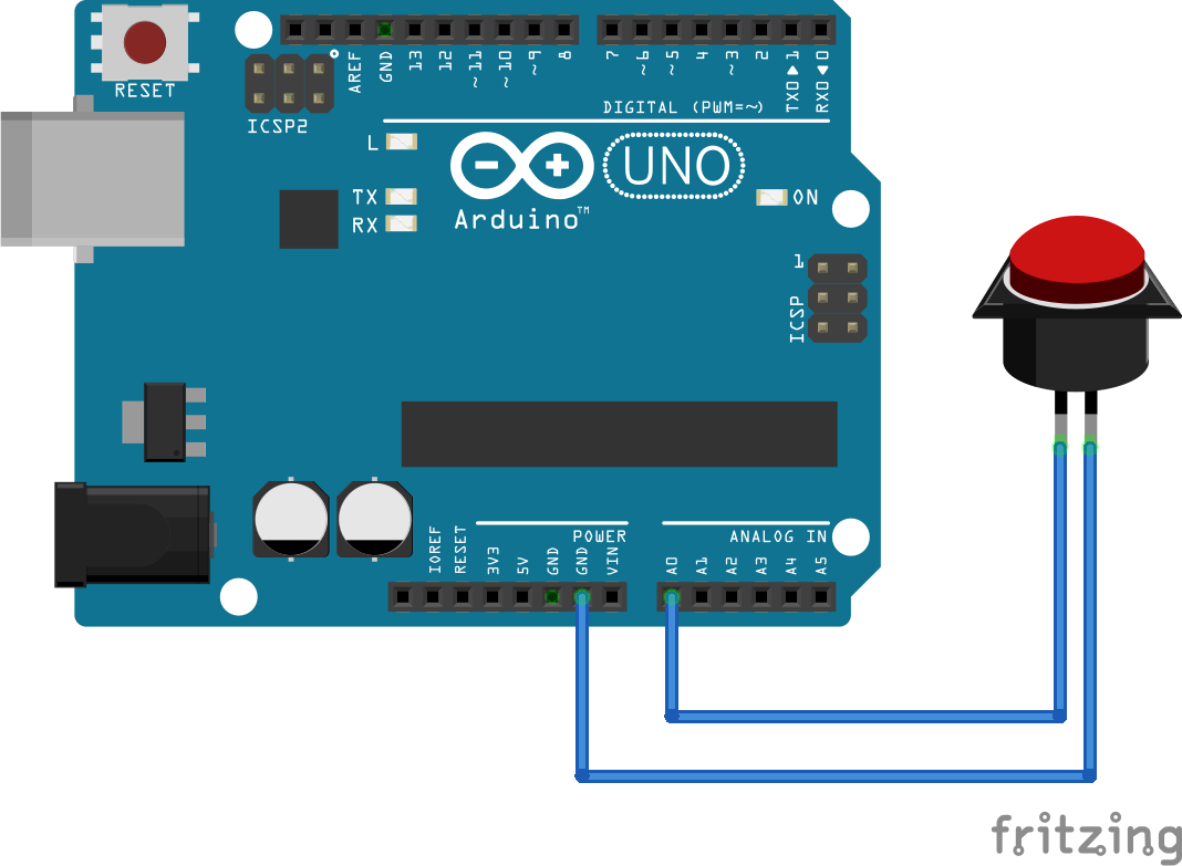
The last part is related to the wiring of the buttons for manual activation and the ON-OFF switch for operating the controller in programmed or manual mode. They are wired using the usual input pullup configurations for arduino digital inputs.
Wiring everything
Replicating the blocks for the required number of electrovalves, leads to the following diagram:
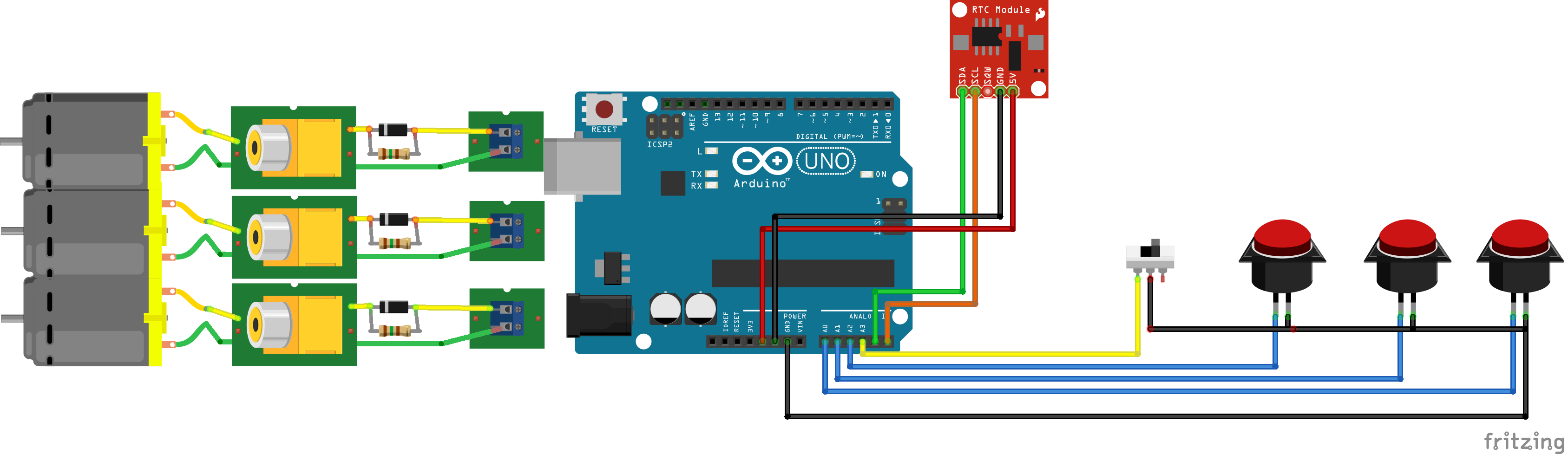
Note that RCA connector and cables are added between the electrovalves and the motor shield outputs. Since most of the digital pins are used by the motor shield, pushbuttons are wired to A0, A1 and A2, while ON/OFF switch is wired to A3. A4 and A5 are used for i2c communitation with the clock module.
The code
Once the circuit and wiring is complete. It is now time to write down the arduino sketch. The program has to:
Allow to choose to operate either in manual or programmed mode, depending on the ON/OFF switch position
If in manual mode, pressing a pushbutton opens the corresponding valve, pushing it again, closes it.
If in programmed mode, the user can choose a time for opening the valve and how much time should be left open.
Upon these requirements, I wrote the sketch to control the sprinklers that you can download from sprinkler_controller.ino. In order to set your favourite activationa and deactivation times, you should edit the arrays in variables start_hour, start_minute and open_time, where open_time is expressed in minutes.
Also note that, before using the code, you should program your ds3231 RTC module, you can use this guide.
Final touches
For installing the controller in place, I used an IP66 electrical box attached to the wall in a repaired place, then I passed the RCA cables in a buried trace leading to the electrovalves box. I powered the controller with a 12v stabilized power adapter, so I added a 9v voltage regulator before wiring it to the controller. Since I generally water the garden late in the evening, the power adapter is connected to a light controlled switch. In this way the controller is powered only from the evening.
That's all. If you have questions or doubts, please leave a comment or send me an email. Thank you!